What is a transformer
The history of the transformer began to develop in the 19th century. The principle of the transformer is basically simple and is based on the laws of induction, which were declared in 1833.
A transformer is a non-rotating electrical device that works on the principle of electromagnetic induction (a phenomenon in which an induced electromotive voltage and an induced current occur in a conductor). It is used to convert the electrical energy of a certain voltage into the electrical energy of another, or even the same voltage, if the goal is to galvanically separate two electrical circuits.
The transformer changes the current voltage and voltage ratios in the circuit while maintaining the frequency stays the same. It works only with a voltage that changes over time, means AC or DC pulsating voltage. During the transformation, the performance does not change if we do not consider the losses of the transformer, which consume a small part of the active power in the transformer itself.
In practice, single-phase and three-phase transformers are mostly used.
Production of custom transformers for the electrical industry
Different electronic devices have individual requirements of special equipment, therefore it is necessary and more advantageous for them to produce a custom transformer. You can read more about the production of custom transformers here.
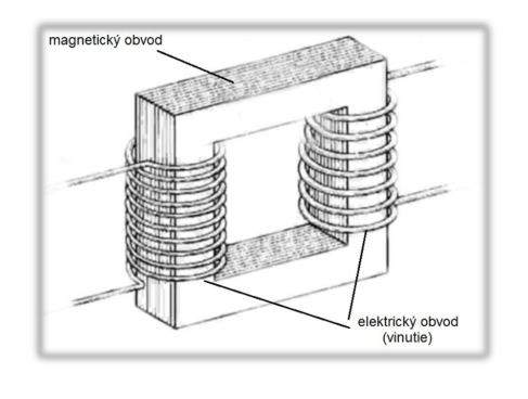
Fig.1 Basic parts of the transformer – design of the windings (a set of windings, which forms an electrical circuit and is connected to one of the voltages for the transformer or choke coil) of the transformer, the magnetic circuit and the configuration (1) (3).
Transformer composition
Transformer composition
The transformer consists of two or more circuits (windings) and one mutual magnetic circuit (core – a ferromagnetic core is mostly used), which serves as a structural element.
Transformers connected to the electrical distribution network are, in addition to the winding safety, covered with another insulating layer, or are embedded in a suitable potting substance.
The purpose of the transformer is to reduce, increase or make the same voltage and its significance lies in:
- reducing investment costs,
- savings over long-distance transmission,
- safety in electricity consumption.
The well-known discoverer Michael Faraday described the idea of a magnetic field in such a way that the magnetic flows creates the sum of induction lines passing through the investigated space, in our case through the coil cross-section (passive electrical element, which is a real representation of inductance in an electrical circuit). The same flow occurs around the coil, but in the opposite direction. The magnetic induction lines are closed lines and therefore the number passing through the cross-section of the coil returns to the space outside the coil. The size of the magnetic flow can be determined by the number of induction lines inside and outside the coil.
Transformer diagram
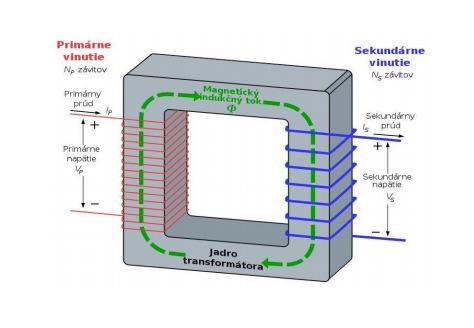
Fig.2 Principle of single-phase nuclear transformer
The unit of magnetic flow is the volt second.
Magnetic field
A magnetic field is a physical field in which the field quantities are the intensity of the magnetic field and the density of the magnetic flux. A magnetic field exists at some point if there is a strength that reacts on the moving electric charges or magnets at.
The magnetic field is manifested by a strength acting on iron objects or other magnets. It is located around a permanent magnet or around a conductor through which an electric current flows (where the field of the permanent magnet is actually caused by the movement of charges inside the atoms) and is graphically represented by magnetic field lines (induction lines).
The magnetic field is characterized by magnetic induction, which indicates the number of induction lines per unit area in a relation. The main magnetic field in transformers is concentrated in the iron core because it has a much better magnetic conductivity than air. The induced magnetic flux is proportional to the magnetic conductivity of the circuit and the strength which caused it, which we call the magnetometer power.
The magnetomotive power, also called flow or ampere thread (given in ampermeters) is the sum of currents passing through the excitation, the so-called magnetic circuit window. The magnetic conductivity of a circuit is the ratio of the magnetic flux and the magnetomotive power that causes it. Numerically equal to the size of the magnetic flux induced by the current of one ampere (7).
Types of transformers
According to the shape of the core, transformers are divided into:
Core transformers
Shell transformers
Toroidal transformers
1. Core transformers
This core type of transformers is used for higher performance. The primary and secondary windings are on different columns of the core.
2. Shell transformers
The winding is located on the middle column, which has the largest cross section. The magnetic flux is distributed symmetrically into the connector and the two side columns, which have a half cross section.
The advantage of this configuration is a good distribution of the magnetic flux and small scatterings, simple winding on one coil and a relatively easy fastening of the core bundle. The disadvantage is poor cooling.
3. Toroidal transformers
The base of the toroidal transformer is a circular core made of steel strip in different widths depending on the required final dimensions and power of the transformer. The winding is located around the whole circuit of the toroidal core.
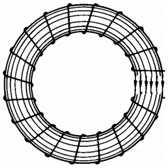
Toroidal transformer
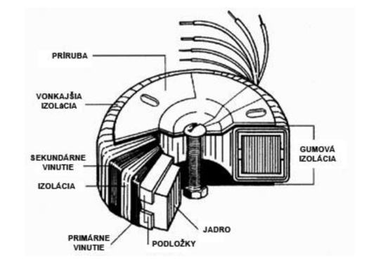
FIG. 3 Powerful toroidal transformer
Construction of small single-phase transformers
A transformer is a device that converts alternating currents and voltages with the same frequency, belongs to non-rotating electrical machines and works on the principle of electromagnetic induction.
According to the current assembly transformers are divided into:
- Single-phase transformers
A single-phase transformer consists of two coils that share a mild steel core. The primary coil is connected to alternating current, which creates a variable magnetic field in the transformer core.
The three-phase transformer has a core with three columns, on one column there can be two or three windings, which are connected to each other by two magnetic connectors. A three-phase transformer is used to transform a three-phase current.
The principle of operation is exactly the same and the construction is very similar to a single-phase transformer. Each phase has its own primary and secondary coil, and they all have one and the same common core, just like a single-phase transformer. The primary as well as the secondary coils are connected to each other either in a star or triangle.
A single-coil transformer is also called an autotransformer.
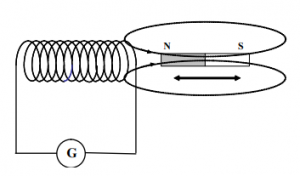
Transformer diagram
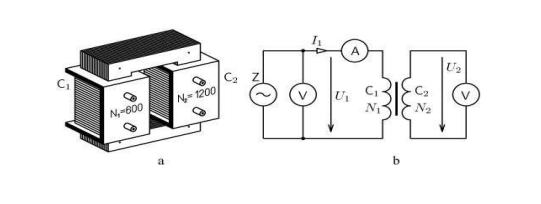
FIG. 4 Illustration of a single-phase transformer and scheme of its insertion. It consists of two separate coils – primary and secondary, which are placed on a common mild steel core. An alternating current is transported to the primary coil, which forms a periodic variable field in the core. Due to the variable magnetic field, an electromotive voltage is induced in the coil threads.
A single-phase transformer is used, for example, in radio, television or measuring instruments.
Three-phase transformers with a similar construction are used to transform three-phase current in power engineering.
Cooling methods of Transformers
Powerful transformers must be cooled, as the winding is heated by the passage of an electric current (passive resistance) and the transformer core is also heated by the eddy magnetic currents.
Cooling is usually:
Direct – the cooling medium circulates around the transformer coil.
Indirect – the coil is separated from the medium.
Refrigerant circulation can be natural or forced. In practice, for transformers cooling we use: air (either passive or through fan), oil, water, inert gas (a gas that is not subject to a chemical reaction under the given conditions), solid insulator (line cooling) or other non-flammable liquids (3).
Voltage measurement by transformer
A measuring transformer is an electrical device that transforms a primary current or voltage into a secondary current or voltage that is suitable for supplying measuring or protective devices with the required accuracy.
Their usage is in power engineering, especially when measuring high voltage and high current circuits, where they adapt the ranges of measuring or protective devices.
The purpose of measuring on the transformer is to determine the losses that occur in it, during the operation. From the losses we calculate the efficiencies and the voltage drop from the load. The transformer incurs iron losses, Joule losses in the windings and additional losses.
The usage of a transformer is very advantageous because, in addition to the transformation defined by the number of turns, the measuring transformer also separates the measuring device (connected on the secondary side) from the primary circuit, which is connected to the measuring circuit.
Measuring current and voltage transformers transform large rotating voltages and currents into values suitable for direct measurement using measuring instruments, so we use them to change the ranges of alternating voltmeters. These transformers also separate the measuring instruments from the measured voltage circuits. Voltage measuring transformers are used to increase and decrease ranges. The primary winding is connected parallel to the circuit whose voltage we want to measure. The nominal secondary voltage of the voltage measuring transformers is 100 V, exceptionally 110 V. We connect the measuring device to the secondary side. The primary voltage can reach up to 400 kV.
We divide them according to the purpose of measurement into current and voltage, and their operation is based on the principle of operation of a common transformer.
In a three-phase transformer we identify:
- measurement of winding resistances
- measurement of voltage transfer
- no-load measurement
- short – circuit measurement (6).
Coil
The coil is a passive electrotechnical element, which is a real representation of inductance in an electrical circuit. It consists of an insulated conductor wound (the winding can be single-layer or multi-layer) on a non-conductive carrying frame.
We divide the coils by its construction, shape, number of turns, but the most basic division it’s by its core (without core – air and with core – with magnetic circuit).
Use of coil
A coil that uses the strength effects of the magnetic field of a core is called an electromagnet.
The coil has a triple usage, such as:
- electromagnet – to create a magnetic field of electric current, the generated magnetic power is used, drawing in the core (electric bell, electric motor, device control…),
- inductor (inductance carrier) – used to create induction of electric current by magnetic field (LC circuits, radio engineering…),
- to transform the voltage in the transformers – induction creates an alternating magnetic field in the primary coil, which generates an electric voltage in the second coil of the transformer (secondary winding), the voltage ratio is directly proportional to the ratio of the number of coil threads.
Induction coils
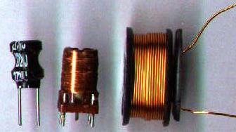
FIG. 5 Different types of coils.
Inductance
The basic physical value of a coil is inductance, which expresses the amount of magnetic flux induced by a given electric current, and depends on the dimensions of the coil, the number of turns and the permeability of the core.
The unit of inductance is henry.
Choke coil
Coil in the shape of a ring, or cylinder is called a choke coil. Choke coil is a coil with a core (usually made of sheet metal or otroperm strips) and a large value of inductance and its purpose is to filter out signals of higher frequencies in an electrical circuit, to transmit signals of lower frequencies and one-way current with low resistance (4) (5).
Choke coil
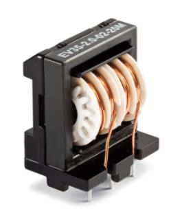
FIG. 6 Choke
Usage of coils
The coils are always intended for a specific targeted product (eg radio receiver, oscillator…) They are not produced in large numbers for different uses.